

Common Safety Risks for Continuous Linear Lighting with LED Tube Cables & Extensions
These risks mostly stem from daisy‑chaining, plug‑in interconnections, wrong accessories, poor installation and environmental mismatch, and may lead to overheating, fire, short‑circuit or electric shock.
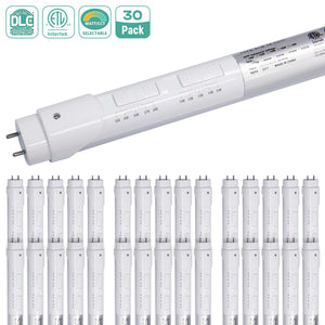
1. Connector‑related hazards (most frequent risk)
- Overheating & arcing from loose / partially inserted plugs Incomplete mating, vibration or cable pulling creates high contact resistance. Connectors heat up, produce electrical arcing, melt plastic housings, and present fire risk.
- Overload of plug‑in terminals by excessive daisy‑chaining Exceeding the manufacturer‑specified maximum number of chained LED tubes. Even if calculated wattage seems low, the internal tube PCB and plug contacts have limited current capacity. Overload causes connector scorching, burnt pins and melting.
- Mismatched or low‑quality third‑party link / extension cables Wrong pin‑out assignment, undersized copper conductors, poor‑quality contact terminals. May cause no illumination, short‑circuit, unexpected overheating even under normal load.
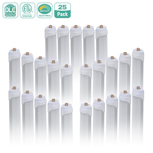
2. Cable risks
- Insulation damage Cables stretched too tight, sharply bent, pinched by mounting brackets, crushed or abraded. Damaged insulation leads to short‑circuit and electric shock hazard.
- Daisy‑chaining multiple short extension cables in series Each plug‑to‑plug joint adds contact resistance. Accumulated resistance raises heat across the whole linear run.
- Modified molded plug‑and‑play cables Cutting, stripping, splicing or repairing factory‑molded extension cables breaks insulation and sealing, introducing shock and short‑circuit risks.
3. Circuit & electrical risks
- Unprotected daisy‑chain segments No dedicated over‑current protection (circuit breaker / fuse) for each lighting segment. A short‑circuit cannot trip protection in time.
- Improper mains tapping Connecting mains power directly inside tube plug‑in connectors instead of certified junction boxes. Exposed live conductors create shock risk.
- Uneven load from degraded tubes A failing LED tube may draw abnormal current, stressing downstream cables and connectors in the daisy‑chain.
4. Installation & mechanical risks
- Unsupported hanging connectors Plug joints suspended by cable weight. Gradual pull‑out creates poor contact and arcing over time.
- Concealed plug‑in joints inside walls / ceiling cavities Hidden connectors cannot be inspected. Overheating faults develop undetected, creating hidden fire hazard.
-
Thermal trapping Combustible materials (insulation, fabric, wood) pressed against tubes and connectors. Heat cannot dissipate, accelerating ageing and ignition risk.
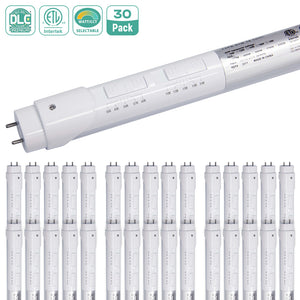
5. Environmental risks
- Wrong IP‑rating for damp / wet locations Standard indoor non‑sealed connectors exposed to moisture, condensation or water spray. Water ingress causes leakage current, corrosion of pins, short‑circuit and electric shock.
- High ambient temperature Installed near heat sources. Accelerates ageing of cable insulation and connector plastic, shortening service life and increasing failure probability.
6. Operational & hidden failure risks
- Progressive degradation without obvious warning Connectors slowly corrode or loosen from vibration; tubes may still light normally while joints quietly heat up, with no visible warning signs.
-
Fault propagation along daisy‑chain One defective tube or bad joint impacts the whole linked run; fault may travel to downstream fixtures.
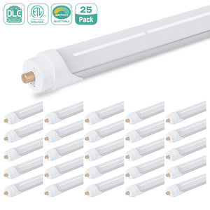
How to Ensure Safety of Continuous Linear Lighting with LED Tube Cables & Extensions
Safety risks for linked LED‑tube linear lighting mainly include connector overheating, short‑circuit, electric shock, cable damage, overload, and fire hazards. Below are systematic safety measures covering component selection, circuit design, installation, operation and environmental adaptation.
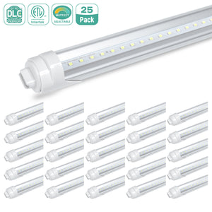
1. Safe Component & Accessory Selection
- Use manufacturer‑matched original link / extension cables Do not use generic non‑matching third‑party cables. Mismatched pin definitions, insufficient contact area or thin conductors can cause poor contact, arcing and overheating. Cables shall carry local safety certification.
- Conductor cross‑section: minimum 0.75 mm² copper for AC link cables; higher cross‑section for high‑wattage long chains.
- Connector rating: plug‑in connectors must exceed the total operating current of one full daisy‑chain segment.
- Select correct IP grade for environment
- Dry indoor: standard PVC cables and connectors.
- Damp, wash‑down or semi‑outdoor locations: use IP‑rated complete sets (LED tubes + mating extension cables + sealed connectors). Ordinary open connectors must not be exposed to moisture, spray or condensation.
- Reject modified or damaged parts Never cut, strip, re‑splice or repair molded plug‑and‑play extension cables. Discard tubes, cables or connectors with cracked housing, bent pins, scorch marks or water ingress.
2. Circuit Design Safety Controls
- Strictly respect maximum daisy‑chain limits Follow the datasheet’s maximum number of linked tubes per chain. Do not exceed it even if calculated total wattage seems acceptable. Internal tube circuit boards and plug connectors have hard current limits.
- When the required linear length exceeds the chain limit: split into multiple electrically‑independent segments, each with separate mains power feed. Visually align tubes for continuous lighting effect, do not electrically daisy‑chain across segments.
- Over‑current protection for each power‑fed segment Every independent lighting segment shall be protected by suitable circuit breakers / fuses, matching total segment load. Avoid overloading one branch circuit with too many linear lighting segments.
- Avoid excessive cascading of long extension cables Minimize stacking multiple long extension cables in one chain. Each extra plug‑in joint adds contact resistance and potential heat points. Use one properly sized longer extension instead of several short ones joined together.
- Power input rules Integrated AC LED tubes take mains supply directly. Make mains connections inside certified junction boxes. Do not tap mains power by twisting bare wires inside tube plug‑in connectors.
3. Installation‑Phase Safety Practices
- De‑energize all wiring work Carry out all cable connection, linking and tube mounting with mains power completely disconnected. Lock‑out / tag‑out for commercial sites. Complete bench power‑on test before final fixing.
- Mechanical protection for cables and connectors
- Do not stretch, pull tight, sharply kink or pinch extension and link cables. Leave small slack for thermal movement and installation adjustment.
- Support cables with cable clips; never let plug‑in connectors hang freely under cable weight. Mechanical pull‑out will create bad contact and arcing risk.
- Do not bury plug‑in connection joints inside walls, ceilings or enclosed cavities. Connectors must remain accessible for inspection and replacement.
- Fully seat all plug‑in connections Push male‑female plugs until they click into locking position. Loose partial insertion is a top cause of connector heating. Check every joint along the linear run.
- Separation from heat sources Keep LED tubes and cable connectors away from hot pipes, heating equipment and direct high‑temperature radiation. High ambient temperature accelerates cable insulation aging.
4. Commissioning, Inspection & Maintenance
- Post‑installation power‑on check After power‑up, observe all connectors for abnormal heat, discoloration, flickering or sparking. Warmth is acceptable; hot or scorching connectors indicate overload or bad contact.
- Regular visual inspection Periodically check:
- Loosened or partially pulled‑out plugs
- Cable insulation abrasion, cracking
- Brown / burnt marks on connector housings
- Water or dust buildup inside connectors
- Fault handling rules If flickering, dimming or hot connectors appear: cut power immediately. Do not continue running the system. Troubleshoot: reduce daisy‑chain quantity, replace defective cables or tubes, re‑seat connections.
5. Compliance & Human Safety
- Follow local electrical codes and standards. For commercial projects, installation shall be performed or verified by qualified electricians.
- Do not install linear LED tube lighting where combustible materials are directly pressed against tubes and connectors; maintain required clearance to combustibles per datasheet.
- Do not place temporary objects, fabric or insulation materials covering tubes and plug‑in joints, which will trap heat and create fire risk.
Quick Safety Checklist (for site reference)
No over‑maximum daisy‑chain tube count , Only original matched link & extension cables used , All connectors fully locked, no hanging unsupported plugs , Plug‑in joints are accessible, not concealed inside cavities ,Correct IP rating matching installation environment , Each segment has proper circuit over‑current protection , No stretched, pinched or modified molded extension cables , Post‑commission thermal check of all connection points。
How to Design Continuous Linear Lighting with LED Tube Cables & Extensions
This guideline covers planning, component selection, wiring topology, voltage‑drop mitigation, installation, and safety for seamless continuous linear lighting using linkable LED tubes, interconnection cables and extension cords。
1. Pre‑Design Planning
1.1 Confirm fixture specifications
- Verify tube type: T5 / T8 linkable‑type LED tubes (integrated AC‑input, daisy‑chain‑enabled). Non‑linkable retrofit G13 tubes cannot be chained by simple extension cables.
- Record tube wattage, operating voltage (100‑277V wide‑voltage AC is most common for linkable tubes), maximum allowed daisy‑chain quantity per manufacturer datasheet.
- Measure total linear run length, mounting gaps between tubes, corner offsets, and main power feed positions.
1.2 Select interconnection & extension cables
- Short link cables: Direct end‑to‑end linking between adjacent tubes (0.15‑0.5 m), for near‑seamless continuous lines.
- Long extension cables: Bridge gaps, offset runs, corner transitions (0.5‑2 m), 3‑pin male‑to‑female molded plug‑and‑play cables matching your tube connector footprint.
- Conductor cross‑section: ≥0.75 mm² copper core for AC link cables; avoid ultra‑thin cheap cables for long chained runsAliExpress.
- Environment match: Indoor PVC‑jacket for dry spaces; select IP‑rated cables & connectors for damp / semi‑outdoor locations.
Do NOT mix different connector pin‑outs; mismatched pin assignment will cause no‑light or short‑circuit risk.
2. Circuit Topology & Power‑feeding Strategies
Daisy‑chain (series‑link via extension cables)
Main AC power feeds into the first tube. Subsequent tubes connect one‑by‑one with link / extension cables.
Critical constraint: Follow manufacturer’s maximum number of chained tubes. Typical limit: 6‑8 units for T5/T8 linkable tubes. Exceeding causes over‑current, overheating, brightness drop, connector burn‑out.
Multiple‑feed / split‑run solution (for very long linear layouts)
If your required continuous length exceeds the daisy‑chain limit:
- Split the long lighting line into several independent segments.
- Supply mains AC power separately to the start of each segment.
- Visually keep tubes aligned to maintain continuous lighting appearance, while electrically isolated.
For AC‑type linkable LED tubes, voltage drop is far less severe than low‑voltage DC LED strips; the main limiting factor is the rated daisy‑chain load of tube internal circuits and connector current rating.
Layout styles supported by extension cables
- Straight continuous runs: short link cables between tubes.
- Spaced linear runs: fixed‑length extension cables create uniform gaps.
- L‑shape / U‑shape turns: use long flexible extension cables to jump around corners without bending the LED tube body.
3. Key Design Rules
- Observe daisy‑chain maximum count: Never exceed datasheet specified chained tube quantity, even if individual wattage seems low. The internal PCB and plastic connectors have strict current limits.
- Extension cable length: Use the shortest practical extension to complete layout. Extra‑long extension cables add minor contact resistance; avoid cascading many long extensions in one chain.
- Mechanical routing: Do not stretch, pinch, or sharply fold extension cables. Leave slack for thermal expansion and mounting adjustment.
- Seamless visual effect: Position tube housings closely when using short link cables; choose frosted diffuser tubes to hide small connector gaps.
- Power supply rule: Linkable integrated LED tubes run on mains AC; no external DC driver required. Connect main power via proper junction boxes, do not splice raw wires inside tube connectors.
4. Step‑by‑Step Installation Workflow
- Cut off main electrical power supply.
- Mark mounting positions for all LED tubes, route extension / link cables roughly on site for length verification. Pre‑test the full chain on bench before permanent mounting.
- Mount tube fixtures / housing brackets.
- Connect main AC input cable to the power‑in port of the first LED tube.
- Connect link or extension cable between the output port of the prior tube and input port of next tube; push connectors fully home until they click.
- Continue linking along the whole linear run. For split multi‑segment layout, repeat power‑in connection for each segment.
- Secure loose cables with cable clips; avoid hanging connectors unsupported.
- Double‑check all plug‑in connections are fully seated. Power on and inspect: all tubes should light evenly, no flickering, no hot connectors.
- Final fix tubes and cables in place.
5. Common Failures & Troubleshooting
| Symptom | Root Cause | Fix |
|---|---|---|
| Last tubes dim / flicker | Too many tubes daisy‑chained; loose connector | Reduce chain quantity; re‑seat plugs; split into multi‑feed segments |
| Individual tube no light | Bad contact in extension cable plug; damaged cable | Swap extension cable; inspect pins for deformation |
| Connector gets hot | Over‑maximum daisy‑chain load; poor insertion | Reduce number of chained fixtures; ensure connectors fully locked |
6. Safety & Compliance Notes
- All installation should comply with local electrical codes; professional electrician recommended for commercial projects.
- Do not modify, cut or re‑wire molded factory extension cables; use purpose‑made matching link accessories.
- Keep connectors away from pooled water. For wet environments select IP‑rated complete system (tubes + matching extension cables).
- Leave access space for connectors; do not bury plug‑in joints inside wall or ceiling cavities.


